
 Esperanto
 Shqiptare
 Euskara
 Zulu
Zulu
 Latinus
 Cymraeg
 தமிழ்
தமிழ்
 Slovak
 Slovak
 Afrikaans
APPLICATION INDUSTRY
APPLI
INDUSTRY
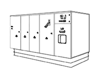
WIND POWER CONVERTERS DISSIPATE HEAT
The wind power converter uses the rotor of the doubly-fed asynchronous wind generator to excite, which makes the amplitude, frequency and phase of the stator side output voltage of the doubly-fed generator the same as the power grid, and the active and reactive power can be independently decoupled as required. The converter controls the doubly-fed asynchronous wind generator to realize soft grid-connection and reduce the adverse impact of grid-connection and motor from electric current. It can be said that whether the wind power converter runs stably directly affects the stability of the power grid. How to ensure the normal operation of wind power converter, heat dissipation is an indispensable step.
WIND ENERGY CONVERTER COOLING SOLUTION(DCDC 3000W transient solution)
Converter simulation model and related parameters:


Converter simulation model and related parameters:

The infineon internal structure diagram and heating element diagram:
diode:34W; IGBT:91W; total 1500W;
Assuming heat-conducting medium:
7762 thermal grease, thickness is 0.2mm, K=4W/m*K.
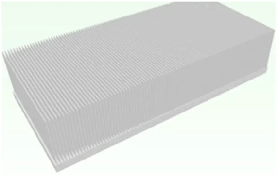
Heatsinkparameter:
Substratesize:462*220*15mm;
Finthickness:1.5mm;
Finqty:92fins;
Finheight:87mm;
Material:AL1060;
Process:Skived;
Runsfor16cycles,atotalof960s。
Heat sink design simulation model and related parameters
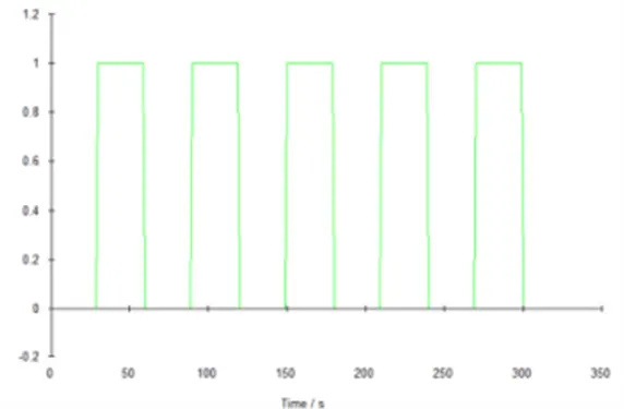
Workingstatusofheatsource:
0-29s:0%;
29s-30s:from0%to100%;
30s-59s:100%;
59s-60s:from100%to0%;
Run60scircularlyatacycle.
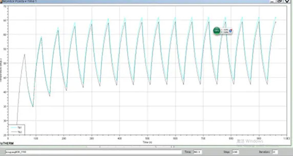
The diagram of Tb temperature over time: ( airflow:500m^3/H)
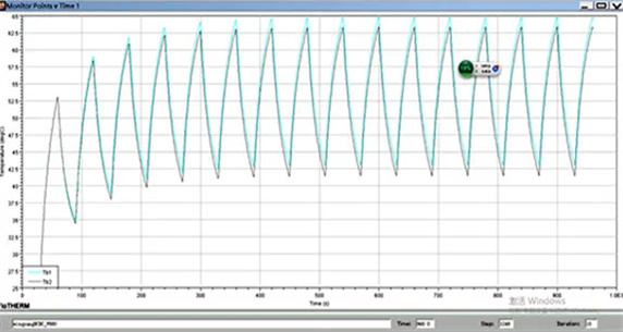
The change diagram of surface temperature over time of IGBT core components:
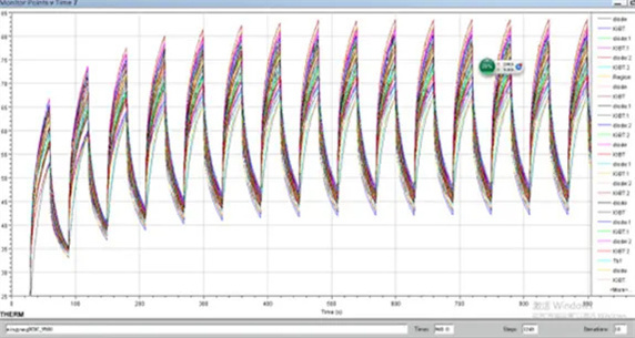
Airflow: 500m^3/H, IGBT node temperature = core element surface temperature + core element power * core element
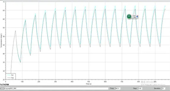
The diagram of Tb temperature over time: ( airflow:600m^3/H)
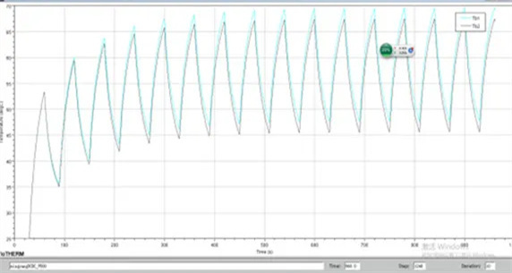
The diagram of Tb temperature over time: ( airflow:700m^3/H)
The diagram of Tb temperature over time: ( airflow:800m^3/H)
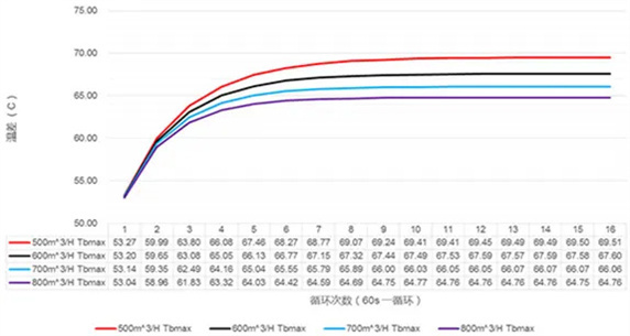
The time cycling variation simulation results of highest surface temperature of heat source bottom radiator:
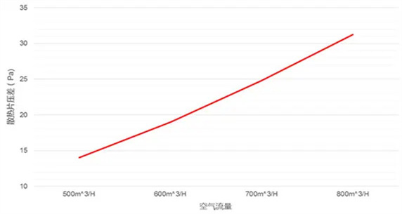
Simulation results of heat sink pressure loss and flow:


Copyright © 2020 Shenzhen Huafu Hardware Products Co., LTD All Rights Reserved
Powered by: www.300.cn