
language
English
العربية
বাংলাদেশ
Български
Hrvatski
Česky
Dansk
Nederland
 Esperanto
Slovenski
Filipino
Suomi
Français
Maori
 Shqiptare
Georgian
 Euskara
Deutsch
Ελλάδα
ישראל
इंडिया
Magyarország
Ísland
Indonesia
Irlanda
Italia
日本語
Sovensko
Հայաստան
한국
Kyrgyz
ປະເທດລາວ
 Zulu
Zulu
Latvian
Lithuanian
Luxembourgish
 Latinus
Macedonian
Малайская
Maltese
Монгол улс
 Cymraeg
ဗမာ
 தமிழ்
தமிழ்
नेपाल
Norge
ایران
Polska
Portugal
România
Российская
Србија
 Slovak
Србија
 Slovak
Bosanski
Slovenian
Беларус
España
Sverige
Точик
ประเทศไทย
Türk
Azərbaycan
Uzbek
 Afrikaans
Việt Nam
APPLICATION INDUSTRY
APPLI
INDUSTRY
IT COMMUNICATION HEAT DISSIPATION
3C product also calls information home appliance, it is to show computer kind communication kind and consumer kind electronic product commonly. Various kinds of market demand are large. China has become the largest consumer market in the world for 3C products. With the improvement of national economic level and income level, Chinese has put forward higher requirements for the quality of electronic products. Businesses have launched products with higher configuration, higher performance and better design to satisfy consumers.
Customer SVG heat dissipation design requirements are as follows
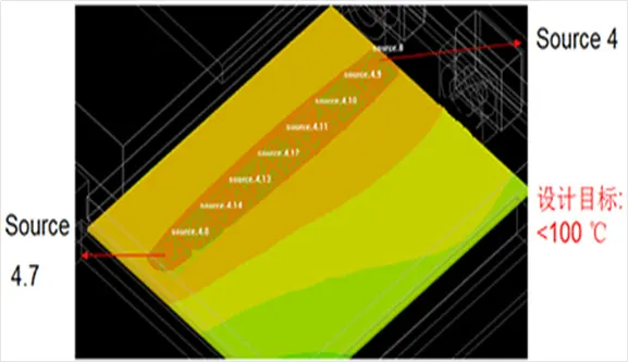
| PCB source Temperature | ≤100℃ |
| CPU Temperature | ≤100℃ |

| DC Output | Conductivity:10W/(m*K) Power:5W |
| CPU Chipset | Conductivity:10W/(m*k) Power:10W |
| PCB MST | Conductivity:15W/(m*K) Power:5W |
| CPU PCB | Conductivity:15W/(m*K) Power:4W |
| CPU Heatsink | Size:125*95*6mm,Substrate thickness:2mm,fin Number: 10pcs, Thickness:0.6mm;Conductivity: AL-extru. 180W/(m*K). |
| CU Block | Size:41*41*4.7,Conductivity:385 W/(m*k) |
| Thermal paste | Thickness: 0.3mm,Conductivity:3.5W/(m*K) |
| Welding mode | Soldering4258,Conductivity:48W/(m*k) 0.2mm |
Schematic diagram of simulation model for overall layout of heat dissipation
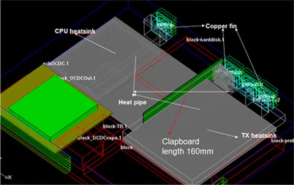
Schematic diagram of simulation model for overall layout of heat dissipation
| Copper fin | Size:30*12*0.3mm,Tilt:1.0,Number:30pcs. |
| Material Science:C1100,Conductivity:385W/(m*K). | |
| Heat pipe | D6 Tube thickness:3mm,Pressing process, heat pipe type: powder sintering,Conductivity:10000W/(m*k). |
| Adding a 30*10 mm axial flow fan, the opening ratio of the new fan opening area 0.7. | |
| A partition | Size:160*33*0.5mm,Material Science: Stainless steel. |
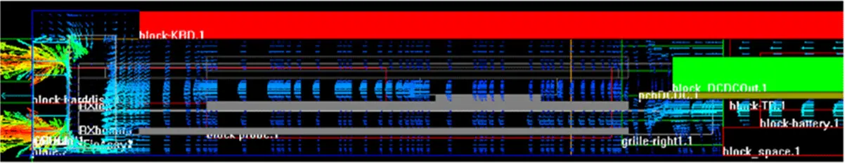
RX Temperature Distribution Diagram of Module Top Simulation

RX Temperature Distribution Diagram of Module Top Simulation
Schematic diagram of simulation model for overall layout of heat dissipation
| NO. | Maximum temperature | NO. | Maximum temperature | NO. | Maximum temperature |
|---|---|---|---|---|---|
| Source 1 | 59.43 | Source 1.7 | 59.73 | Source 3.1 | 59.59 |
| Source 1.1 | 59.54 | Source 2 | 60.02 | Source 3.2 | 59.7 |
| Source 1.2 | 59.66 | Source 2.1 | 60.19 | Source 3.3 | 59.77 |
| Source 1.3 | 59.73 | Source 2.2 | 60.16 | Source 3.4 | 59.8 |
| Source 1.4 | 59.76 | Source 2.3 | 59.96 | Source 3.5 | 59.8 |
| Source 1.5 | 59.77 | Source 2.4 | 59.96 | Source 3.6 | 59.78 |
| Source 1.6 | 59.76 | Source 3 | 59.48 | Source 3.7 | 59.74 |
| CPU Maximum temperature(℃) | Temperature range of heat source(℃) | System airflow(ft^3/min) | |
|---|---|---|---|
| Simulation results of the scheme | 64.43 | 60.92~59.43 | 8.4 |
| It meets the requirements of CPU temperature less than 80 C and heat source body temperature less than 100 C, and completes the heat dissipation design requirements. | |||


Copyright © 2020 Shenzhen Huafu Hardware Products Co., LTD All Rights Reserved
Powered by: www.300.cn
Business license