
 Esperanto
 Shqiptare
 Euskara
 Zulu
Zulu
 Latinus
 Cymraeg
 தமிழ்
தமிழ்
 Slovak
 Slovak
 Afrikaans
APPLICATION INDUSTRY
APPLI
INDUSTRY
ENERGY STORAGE SYSTEM HEAT DISSIPATION
According to the provisions of the State Grid, the proportion of distributed generation such as photovoltaic and wind power should not exceed 10% of the power grid, and more than 10% of the grid will be added to the energy storage system. Because photovoltaic system and wind power system do not use energy storage system in grid-connected power generation, there will be some adverse effects on the grid. If the scale of wind energy and photovoltaic power system continues to expand and the proportion of photovoltaic power in the system continues to increase, these effects can not be ignored. Through the analysis of the characteristics of photovoltaic power generation, it can be seen that the impact of photovoltaic power generation system on the grid is mainly caused by the instability of photovoltaic power supply. In order to make the grid safer, stable and economic operation, it is generally required to install energy storage system. Therefore, the demand for energy storage system has increased in recent years.
Solution of Inverter Heat Dissipation in Energy Storage System:
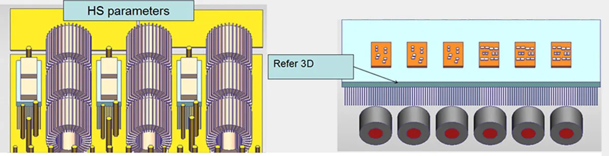
Simulation model and parameter schematic diagram (1):

Composition diagram of inverter module:

Inverter Module Composition, Heating Element Distribution Diagram and Relevant Parameter Diagram:

(Figure) Distribution of RFC heating elements and IGBT power consumption parameters
NV Module parameter:
IGBT:317.2W,No additional heat consumption;
Thermal conductive medium:0.1MM,K=4W/m*K;
IGBT Rjc=0.74K/W,diode Rjc=0.84 K/W

(Figure) Distribution of RFC heating elements and IGBT power consumption parameters
RFC Module parameter:
IGBT:223.8W,No additional heat consumption;
Thermal conductive medium:0.1MM,K=4W/m*K;
IGBT Rjc=0.65K/W diode Rjc=0.86。
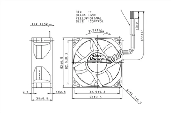
Simulated sketch of fan usage:
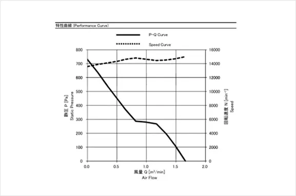
Use Minebea06038DA-12R-EUD-1 15000RPM Fan
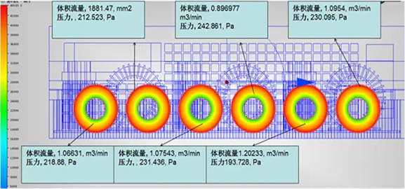
Simulating schematic diagram of radiator placement position of inverters in energy storage system (refer to 3D drawing):
Simulation sketch of cross-section dissipation velocity in inverter radiator of energy storage system:
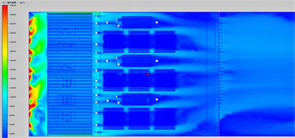
Simulation sketch of cross-section vector dissipation in inverter radiator of energy storage system:
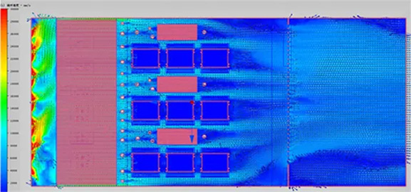
The simulation result and schematic diagram of airflow vector dissipation:
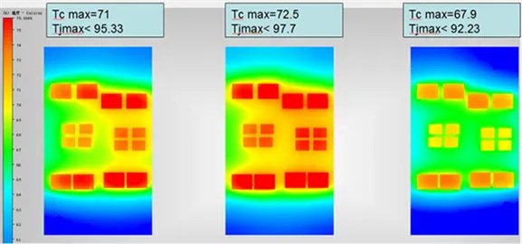
INV Temperature Dissipation Simulation and Schematic Diagram of Modular Radiator:

Temperature Dissipation Simulation and Schematic Diagram of Inverter Radiator:
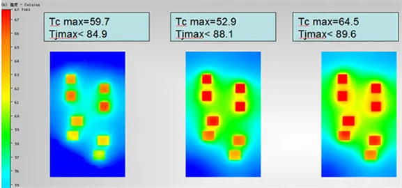
RFC Temperature Dissipation Simulation and Schematic Diagram of Modular Radiator:
| Resolvent |
radiator Floo r temperature |
heatsink temperature rise |
ambient temperature |
IGBT Maximum Saving Temperature and Temperature Difference(℃ ) | |||
|---|---|---|---|---|---|---|---|
| INV | INV Temperature difference | RFC | RFC Temperature | ||||
| Aluminium extrusion heatsinks | 64.6 | 39.6 | 25 | 97.7 | 5.5 | 89.6 | 4.7 |
| Assuming that the thermal conductivity of the conductive medium is 4w/m*k | |||||||


Copyright © 2020 Shenzhen Huafu Hardware Products Co., LTD All Rights Reserved
Powered by: www.300.cn