
 Esperanto
 Shqiptare
 Euskara
 Zulu
Zulu
 Latinus
 Cymraeg
 தமிழ்
தமிழ்
 Slovak
 Slovak
 Afrikaans
APPLICATION INDUSTRY
APPLI
INDUSTRY
PHOTOVOLTAIC INVERTER HEAT DISSIPATION
Inverter is also called power regulator. The process of converting DC power into AC power is called inversion. The circuit that completes the inverting function is called inverting circuit. The device that realizes the inverting process is called inverting equipment or inverter. In solar power generation system, the efficiency of inverters is an important factor to determine the capacity of solar cells and storage batteries. The failure of photovoltaic inverters will lead to the shutdown of photovoltaic system, which will directly cause the loss of power generation. Therefore, high reliability is an important technical index of photovoltaic inverters.
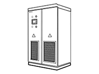
Solution to Heat Dissipation of Photovoltaic Inverter(210KW)
Simulation model and parameter schematic diagram (1):
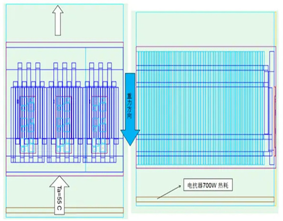
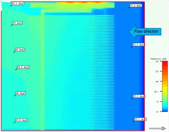
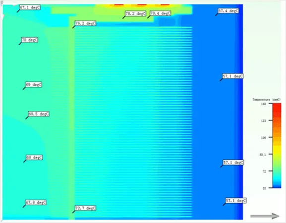
ambient temperature:55⁰C,Reactor Heat Consumption:700W
Assuming the system impedance is 80Pa, the curve of the fan passing through the radiator is as follows:

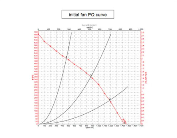
Assuming the system impedance is 80Pa, the curve of the fan passing through the radiator is as follows:

The left figure shows the internal structure of Infineon and the schematic diagram of heating elements.
Diode:59W; IGBT:124.5W; Total:1100WW;
Assuming that the heat conducting medium is:0.15mm Thick,K=3W/m*K.
Assuming the system impedance is 80Pa, the curve of the fan passing through the radiator is as follows:
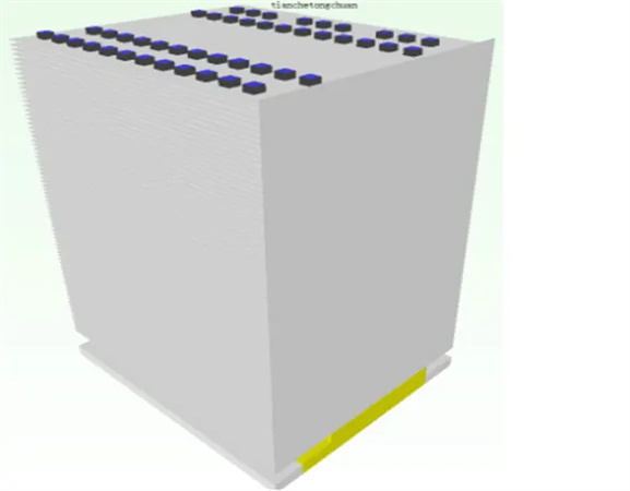
Heatsink parameters:
Size:W236*L200*H304mm
Fin :
Thick:0.6mm
Pitch between teeth:3.0mm
Number of teeth:77fins
Heat pipe parameters:
D8 Sintered tube or fibre tube;
Use 24pcs U heat pipe (one layer layout) and type 48 PCs L heat pipe (two layers layout);
Welding with 4258 low temperature solder paste;
Substrate: AL Plate + Copper Plate (IGBT Heat Source Area)
Compared with two-layer heat pipe, one-layer heat pipe has lower cost and higher heat dissipation efficiency.
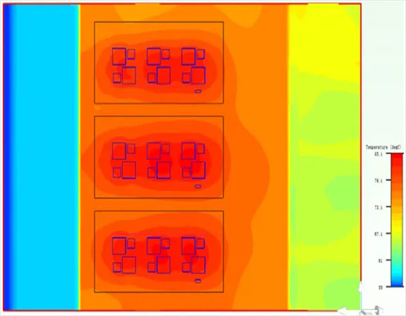
Simulation sketch of pressure diffusion degree of section in module:

Simulation sketch of pressure diffusion degree of section in module:

Temperature Diffusion Simulation Diagram of Section in Module:
Temperature diffusion simulation sketch of top heat pipe:
The temperature difference between the two ends of the heat pipe is 5.7 degrees, which meets the actual heat pipe standard.
Temperature diffusion simulation sketch of bottom heat pipe:

The temperature difference between the two ends of the heat pipe is 9 C, slightly higher than the actual, and the actual performance of the heat pipe will be better than the analysis setting.
Temperature Diffusion of Heat Pipe at the Bottom of Radiator:
The actual air intake temperature of the radiator is ~57.1 C, and the maximum temperature of the radiator bottom is 85.1 C, Theoretical analysis of temperature rise of 28℃
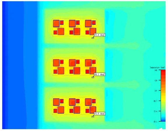
NTC Temperature Diffusion Simulation Diagram of Module:
The temperature difference between the two ends of the heat pipe is 9 C, which is slightly higher than the actual situation. The actual performance of the heat pipe will be better than the analysis setting.
Diagram of Fan Action Point:

Summary of simulation data of photovoltaic inverter cooling scheme:
| Solution | Ta | Power | H.S Tb max |
H.S DT |
HTC1 | HTC2 | HTC3 | Fan working point |
|---|---|---|---|---|---|---|---|---|
| Al base+ copper block |
55 | IGBT/3pcs 1100W/each Reactor 700W |
85.1 | 28 | 87.6 | 88.1 | 87.5 | 1127.5 m^3/Hr 215Pa |
Assuming that the air temperature of the system is 55_C and 57.1_C after entering the reactance, assuming the use of thermal conductive medium 0.15mm,K=3W/m*K)


Copyright © 2020 Shenzhen Huafu Hardware Products Co., LTD All Rights Reserved
Powered by: www.300.cn